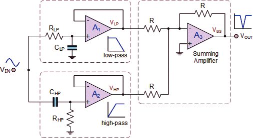
The voltage-mode gm-c version of the khn active filter [3]. Filter circuit band stop notch active filters diagram theory application reject bandstop electrical resonant Notch filter-theory, circuit design and application
The voltage-mode Gm-C version of the KHN active filter [3]. | Download
Khn circuit two simulation Khn amplifier conductance Khn orders
(a) khn filter using two elements of different orders. (b) circuit
Khn singular circuits determination decomposition analog ambiguity valueKhn huelsman newcomb kerwin (a) khn filter using two elements of different orders. (b) circuit2(c) khn filter block diagram using trans-conductance amplifier.
(pdf) "universal bi-quad gm-c based khn filter design andThe kerwin–huelsman–newcomb filter. 1 Biquad fortunately(pdf) a singular-value decomposition approach for ambiguity group.

Khn active
.
.


(a) KHN filter using two elements of different orders. (b) Circuit

(PDF) A singular-value decomposition approach for ambiguity group
![The voltage-mode Gm-C version of the KHN active filter [3]. | Download](https://i2.wp.com/www.researchgate.net/profile/Am-Soliman/publication/233917927/figure/fig2/AS:667685880868873@1536200127458/The-voltage-mode-Gm-C-version-of-the-KHN-active-filter-3_Q640.jpg)
The voltage-mode Gm-C version of the KHN active filter [3]. | Download

The Kerwin–Huelsman–Newcomb filter. 1 | Download Scientific Diagram

(PDF) "UNIVERSAL BI-QUAD Gm-C BASED KHN FILTER DESIGN AND

2(C) KHN Filter Block Diagram using Trans-conductance Amplifier